
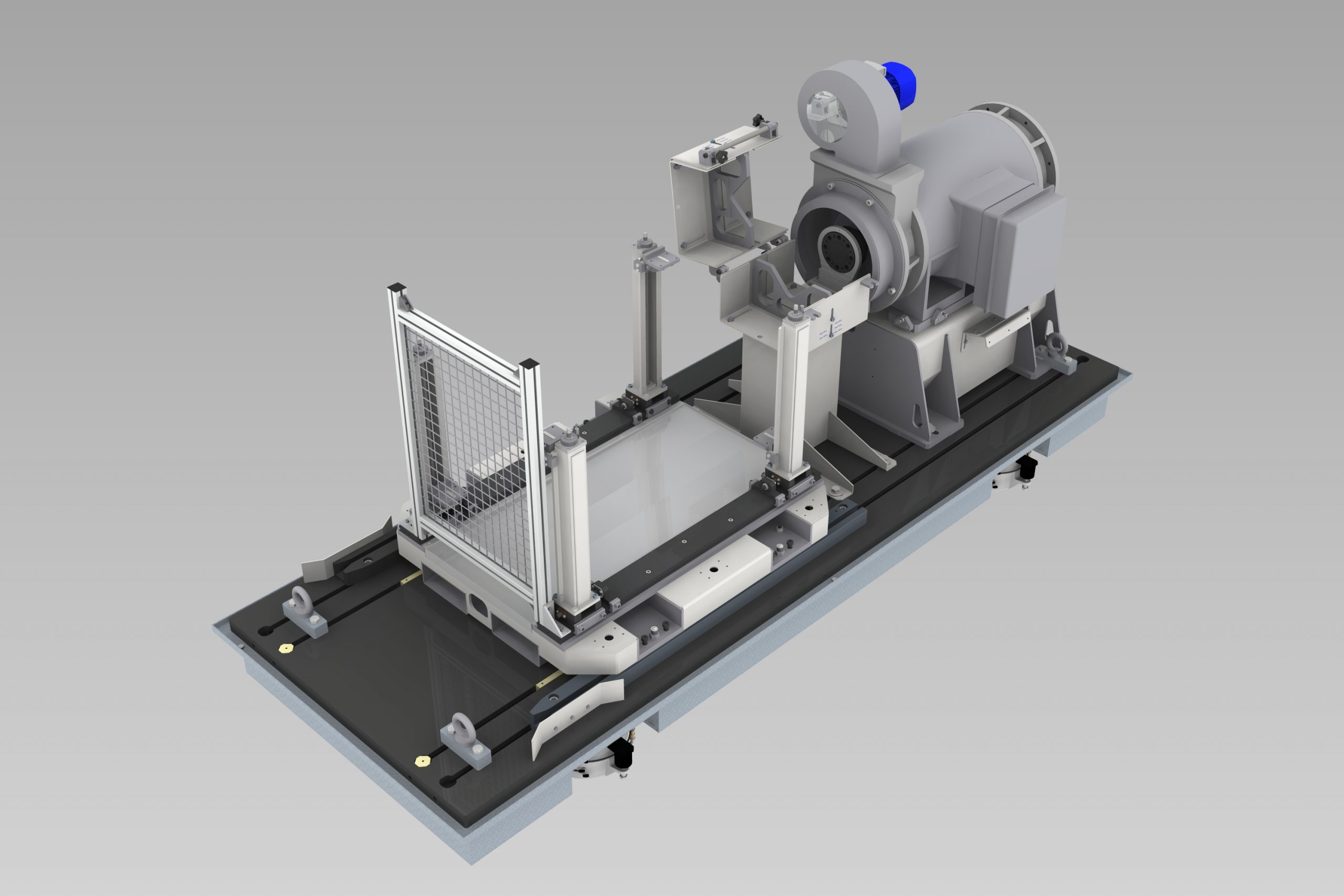
Braking system for engine test rooms
The system proposed by Control Sistem is suitable for any type of engine test room (C.O.P. cells, testing cells, etc.)
The main component of the system is the electric machine which, by dissipating the power generated by the endothermic test engine, exerts the actual braking action. The electric machine is the result of a studied coupling between the electric motor and the power drive, whose synergy is an essential prerogative for achieving the best system performance.
The braking system also comprises a mobile pallet, which is used to position the endothermic engine inside the room, and a base-plate with anti-vibration characteristics on which both the pallet and the electric motor with its support are placed.
Electric motor
The electric motors (or dynamo) are typically of the three-phase asynchronous type, with low inertia rotors and lamellar stators provided with a self-supporting magnetic block. The function of the electric motor is to absorb energy from the internal combustion engine or to generate it for start or entrainment purposes.
The main goal of the dynamo is to satisfy particular types of applications where high torque and speed regulation performances are required. Its support consists of a mechanical structure (frame) built with iron and sheet metal welded together. The purpose of this support is to fix the dynamo on it, so as to have the centre of the transmission at the desired height. This support can be fixed directly on the base by means of screws or "T" nuts.
The transmission shaft that connects the dynamo to the internal combustion engine is repaired by a specific cover system designed by Control Sistem, able to protect people and other equipment, in case of shaft breaking. Thanks to an electrical safety signal connected to the automation system, the engine is guaranteed to stop if the cover is not properly closed.
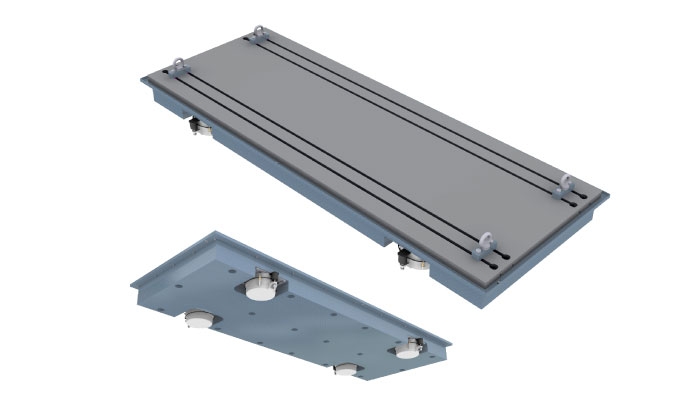
Anti-vibration support
In order to ensure long-term stable test operation and to reduce wear resulting from the vibration of the internal combustion engine, both the latter and the dynamo must be mounted on a single insulated support. Control Sistem solution allows it.
In its standard edition, this unit rests on four air springs, which are designed to reduce the vibrations transmission to the building. The equipment is mounted in line on stainless steel guides on which all the components can be moved and adjusted. In this way all the parts of the "engine - shaft - dynamo" unit are positioned towards each other without a relative movement.
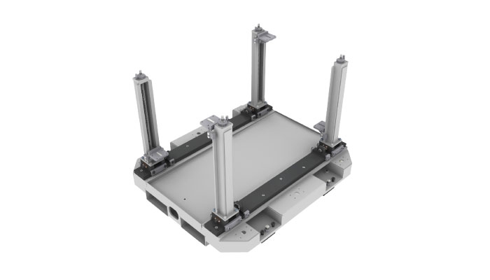
Engine pallet
The growing variety of engine sizes, especially in the passenger car sector, requires a test environment with high flexibility, able to ensure correct engine assembly and positioning inside the rooms.
The engine pallet must necessarily cope with this variety: a flexible pallet improves the availability of the test cell and increases the efficiency of the entire system.
This flexibility is achieved thanks to a combination of horizontal and vertical profiles, which allows you to adapt the engine brackets in different heights and positions and therefore to adjust the pallet with respect to the dimensions of the engine itself. Furthermore, the engine pallet proposed by Control Sistem allows a good alignment of the engine with respect to the dynamo, by means of simple adjustment screws.